


Electrochemical Experimental Systems Explained: Why Are Your Data Unstable?

Electrochemical Experimental Systems Explained: Why Are Your Data Unstable?
An Engineering-Oriented Selection Guide from 2-/3-/4-Electrode Systems to Rs and iR Drop
Introduction
Unstable electrochemical results are often not caused by poor materials, but by uncontrolled system boundary conditions. A slightly misplaced reference electrode, a marginally higher solution resistance, or partial polarization of the counter electrode can shift entire curves, move peak positions, and distort impedance spectra. What appears to be a “material problem” is very often a case of the system itself changing.
This article breaks down the electrochemical experiment as a reusable engineering system. We cover electrode configurations (two-, three-, and four-electrode systems), cell structures (open, sealed, and H-type separated cells), and the most frequently overlooked yet most influential parameters: electrode spacing, solution resistance (Rs) and iR drop, electrolyte volume, atmosphere, and temperature. You will gain a clear selection logic and troubleshooting workflow to achieve more comparable and reproducible electrochemical data with fewer trial-and-error cycles.
1. Overview of Electrochemical Experimental Systems
1.1 What Is an Electrochemical Experimental System?
An electrochemical experimental system is fundamentally an engineering platform designed to apply a controlled potential or current while simultaneously measuring the electrochemical response of the system. The objective is not to assemble complex hardware, but to obtain reliable signals under controlled, repeatable conditions.
1.2 Four Core Components
2. Electrode Configurations Explained: 3-, 2-, and 4-Electrode Systems
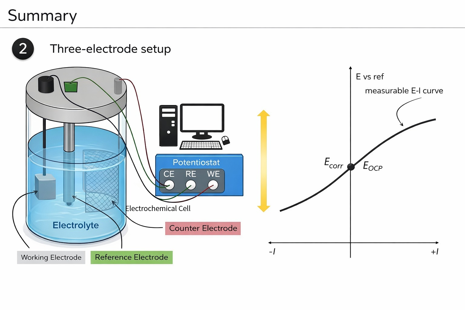
2.1 The Three-Electrode System: Why Research Relies on It
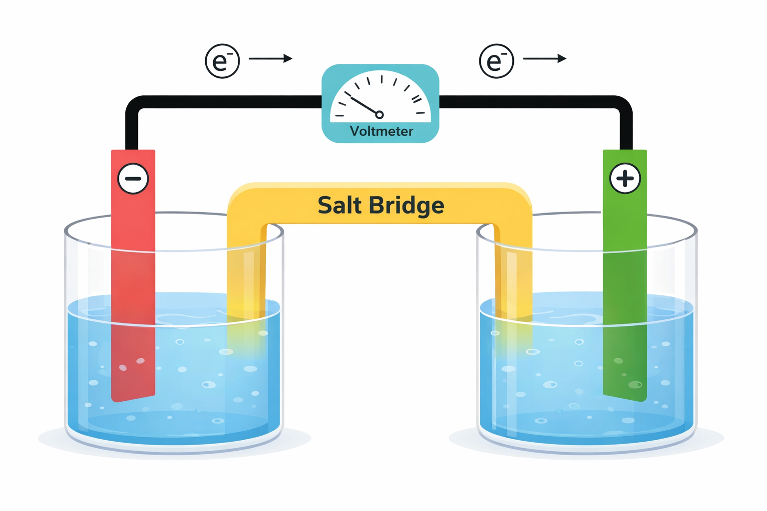
Many people first learn “electrodes” from batteries. A battery is a typical two-electrode system, where the focus is stable overall output—not what happens at a single electrode at a precise potential. This is why researchers often ask: why add one more electrode?
The answer lies in purpose: two-electrode systems are built to operate, while three-electrode systems are built to measure. Three-electrode configurations are designed to make electrode processes quantitative, comparable, and reproducible.
2.2 Why Two-Electrode Systems Are Limited for Precise Measurements
Two-electrode systems are not “wrong”; they simply optimize for different goals. But for research measurements, they face structural limitations:
- The working electrode potential cannot be independently and precisely controlled.
- Counter electrode polarization directly enters the measured signal.
- iR drop and polarization effects mix together and are difficult to separate.
As a result, the signal often contains both intrinsic material behavior and system artifacts “stacked” together, which makes reproducibility difficult.
2.3 How the Three-Electrode System Solves This
The three-electrode system introduces a reference electrode and separates potential measurement from the current path:
With this functional separation, the working electrode potential can be precisely controlled and measured without being directly affected by current flow. This is the most fundamental difference between three-electrode and two-electrode systems.
2.4 Two-Electrode Systems: Engineering-Oriented Configuration
A two-electrode system contains only a working electrode and a counter electrode. In this setup, the counter electrode also acts as the “reference.” Advantages include simple structure, easy wiring, and alignment with real devices. It can be preferable for battery tests, industrial electrolysis/plating, supercapacitor evaluation, or conductivity measurement where absolute potential is not critical.
2.5 Four-Electrode Systems: Removing Resistive Artifacts (Kelvin Method)
When system impedance is extremely high (e.g., solid electrolytes) or series resistance dominates, even three-electrode setups may be insufficient. Four-electrode (Kelvin) methods separate current-driving and voltage-sensing circuits using two electrode pairs, greatly reducing voltage drops from solution/contact/bulk resistance and enabling measurement of intrinsic properties.
3. Types of Working Electrodes and Material Selection
This chapter focuses on selecting the working electrode (WE) as the source of your measured signal. WE material determines background current, potential window, and interfacial kinetics. The indirect impact of cell structure materials (caps, seals, housings) is covered separately in Section 6 as environmental boundary conditions.
The working electrode is where the reaction truly occurs and is the direct origin of electrochemical signals. Material choice determines the usable potential window, reversibility, background current level, and ultimately data stability and reproducibility. There is no universal “best working electrode”— selection should balance conductivity, stability, activity, and controllability based on your experiment objective.
3.1 Common Working Electrode Materials
- Platinum (Pt): high conductivity and chemical inertness; fast kinetics; may evolve hydrogen at low potentials in acidic aqueous systems, interfering with cathodic analysis.
- Gold (Au): stable at positive potentials; commonly used for surface modification (e.g., SAMs) and thiol-related detection.
- Silver (Ag): useful in cyanide/sulfide systems; potential window is relatively limited.
- Glassy Carbon (GC): wide potential window; strong mechanical and chemical stability; one of the most common lab electrodes.
- Graphite: low cost and high conductivity; common in industrial processes and battery research; surface structure can be complex, affecting reproducibility.
- Carbon Paste Electrode (CPE): easy to dope/modify; useful for enzyme electrodes and chemically modified electrodes.
- Emerging carbon materials (BDD, CNTs, graphene, etc.): potentially wider windows and stronger anti-fouling behavior; suitable for high-sensitivity sensing and frontier research but higher cost/complexity.
- Mercury (Hg): high hydrogen overpotential; suitable for cathodic reduction and polarography; usage is increasingly restricted due to toxicity and environmental concerns.
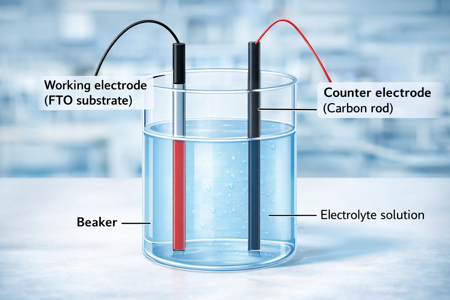
- ITO / FTO conductive glass: conductive and transparent; common in photoelectrochemistry and photocatalysis.
- MXene / MOF composites: widely used in frontier research for energy storage and electrocatalysis as emerging working electrode materials.
3.2 Practical Principles for Working Electrode Selection
Choose the working electrode using an engineering decision framework:
| Factor | Engineering Guidance |
|---|---|
| Potential window | Ensure the target reaction lies within the inert region of the electrode material; avoid HER/OER and electrode dissolution. |
| Chemical stability | Remain non-reactive and insoluble under the chosen electrolyte (strong acid/base, non-aqueous solvents). |
| Electron transfer rate | Provide sufficiently fast interfacial kinetics for the redox couple of interest. |
| Surface area & geometry | Disk electrodes are common; porous/high-area structures increase sensitivity but can reduce reproducibility. |
| Application context | Corrosion often uses the actual metal; sensors often prefer modifiable carbon substrates. |
4. Selection Logic and Electrochemical Cell Structure Design (Practical)
4.1 Fast Selection Rules (Quick Judgement)
- Research vs. engineering: mechanism/kinetics → prioritize three-electrode; device-level evaluation → two-electrode can be acceptable.
- Need separation: counter electrode products may interfere or you need product collection → choose H-type / membrane-separated cells.
- Air/moisture sensitivity: non-aqueous or air-sensitive chemistry → sealed cell + inert gas (N₂/Ar) + reliable seals.
- High current / long duration: larger volume, larger counter electrode area, robust mounting and temperature control to prevent concentration drift.
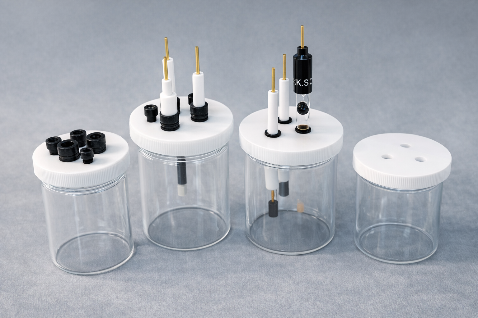
4.2 Electrochemical Cell Design
The electrochemical cell is the physical carrier that holds electrolyte and fixes electrode geometry. It does not directly determine reaction mechanism or intrinsic material properties, but it strongly affects stability, reproducibility, and data credibility. Many “drift” and “poor repeatability” issues originate from inappropriate cell structure or selection—not from electrode materials themselves.
- Provide the reaction environment (electrolyte solution / molten salt / solid electrolyte).
- Fix electrode positioning to keep WE/RE/CE geometry stable.
- Enable separation and transport control (membrane, salt bridge, compartments).
- Maintain stable boundary conditions for stirring, gas purging, temperature control, and sealing.
- Two-electrode cells: simple; suitable for batteries/industrial electrolysis; limited for accurate WE potential control.
- Three-electrode cells: the most common research cell; supports CV/LSV/CA/EIS.
- H-type separated cells: cathode and anode compartments separated by membrane or salt bridge; prevents cross-interference and supports product analysis/collection.
- Sealed vs. open cells: sealed for non-aqueous/air-sensitive/volatile systems; open for routine aqueous experiments and teaching labs.
- Cell body: borosilicate glass for general use; PTFE/PEEK/PVDF for strong acids/bases and organic solvents.
- Ports & accessories: PTFE caps with multi-ports, O-ring sealing, gas inlet/outlet, temperature probe, stirring port, etc.
- Volume selection: common sizes 10 mL / 50 mL / 100 mL / 250 mL. Too small a volume can cause concentration drift and instability.
5. Key Parameters That Decide Whether Data Are “Controllable and Comparable”
5.1 Electrode Distance and Electrolyte Volume (Remember This First)
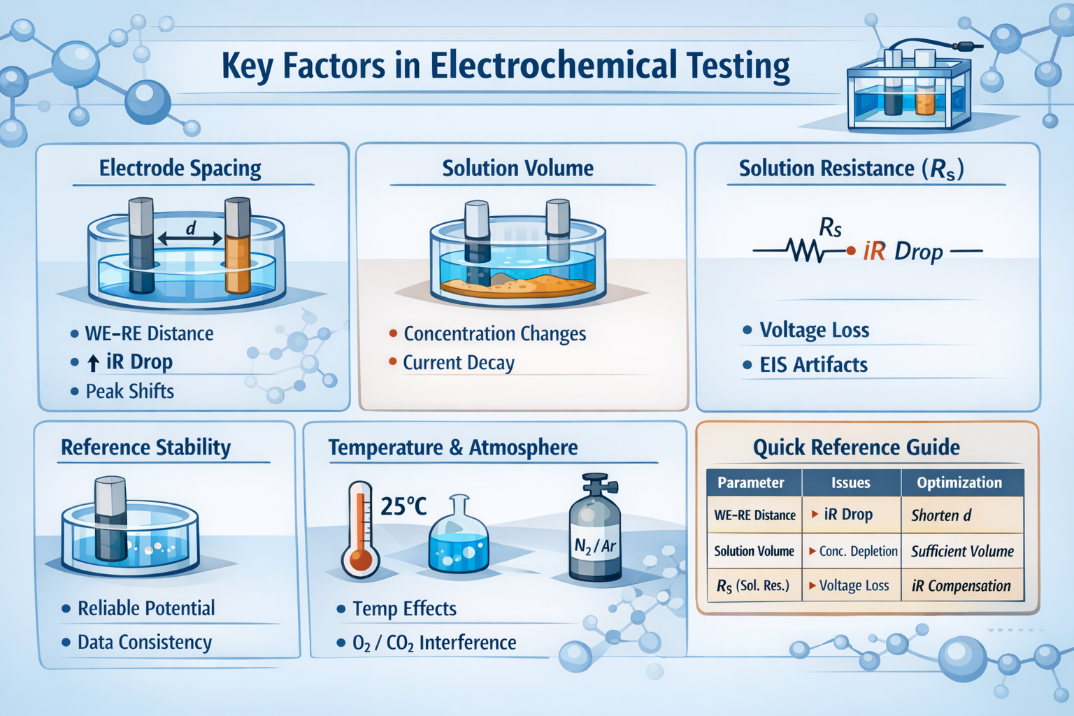
Electrode spacing and electrolyte volume directly influence data accuracy and reproducibility. Excessive spacing increases solution resistance, causing significant iR drop so the actual WE potential deviates from the set value. This often manifests as CV peak shifts, peak broadening, and increased Rs in EIS. Too small an electrolyte volume leads to rapid reactant depletion and product accumulation, changing concentration over time, causing current decay, baseline drift, or even “false irreversibility.” Therefore, place the RE as close as possible to the WE and ensure sufficient electrolyte volume for stable and comparable results.
Analogy: Electrode spacing in electrochemistry is like optical path length in spectroscopy. Longer path length increases signal attenuation and distortion; similarly, longer resistive paths increase iR drop and distort measured potential. The purpose of shortening both is to reduce transmission losses and measurement artifacts.
5.2 Electrode Spacing (WE–RE)
Electrode spacing here primarily refers to the distance between the working electrode (WE) and reference electrode (RE). It determines the resistive path length and is a key geometric factor for potential control precision. Larger distance → higher Rs → larger iR drop → actual potential deviates from the set value. Typical symptoms include peak shifts, peak broadening, and increased solution resistance in EIS.
Optimization: Move the RE closer to the WE. If needed, use a Luggin capillary.
5.3 Solution Resistance (Rs) and iR Drop
Solution resistance (Rs) is the ohmic resistance experienced by current flowing through the electrolyte. The iR drop is the voltage loss caused by current (i × Rs). The set potential does not fully appear at the WE interface—part of it is consumed as resistive loss. When Rs is large or current is high, the effect becomes significant, leading to peak shifts, apparent overpotential increase, and distorted impedance results.
Optimization: Shorten electrode spacing, increase electrolyte conductivity, and apply iR compensation within a reasonable range.
5.4 Reference Stability (Decides Potential Comparability)
The reference electrode provides a stable and reproducible potential baseline. If the reference potential drifts or changes state, the entire curve shifts, destroying comparability. Maintain and verify reference performance to ensure stable potential during measurements.
5.5 Temperature and Atmosphere Control
Temperature affects electrolyte conductivity, kinetics, and interfacial state, causing changes in current/potential response. Atmosphere—especially dissolved O₂ and CO₂—can introduce side reactions or alter solution chemistry, shifting results away from the intended system. For high precision, use temperature control and inert gas protection (N₂/Ar).
5.6 Engineering Quick Reference Table
| Parameter | Primary Impact | Common Symptoms | Engineering Fix |
|---|---|---|---|
| WE–RE spacing | Potential control accuracy | Peak shift, broadened peaks | Shorten distance; use Luggin if needed |
| Rs | Actual interfacial potential | iR artifacts, overpotential appears high | Shorten distance; increase conductivity; iR compensation |
| Electrolyte volume | Concentration stability | Current decay, baseline drift | Use sufficient volume to avoid concentration change |
| Scan rate / time scale | Kinetics vs transport | Rate-dependent peak shift/shape change | Run multi-rate tests to identify control regime |
| WE effective area | Current density | Non-comparable current | Standardize polishing; report current density |
| Surface state | Electron transfer | Curve changes over cycles | Fix pretreatment protocol; distinguish activation vs decay |
| Electrolyte composition | Double layer / migration | Asymmetric CV, abnormal background | Adequate supporting electrolyte; consistent ionic system |
| Convection/stirring | Mass transfer | Unstable peak current | Keep still or use RDE when needed |
| Reference stability | Potential comparability | Whole curve shifts | Maintain junction; periodically verify reference |
| Temperature | Kinetics & conductivity | Drift in current/potential | Use temperature control; keep consistent across runs |
| Atmosphere (O₂/CO₂) | Side reactions | Extra redox peaks | Deoxygenate; inert gas protection |
| Test history/order | Memory effects | Inconsistent before/after | Fix test sequence; avoid cross-contamination |
| Instrument range/settings | Signal realism | High noise / saturation | Keep in linear range; proper filters |
| Mounting repeatability | Geometry consistency | Large batch-to-batch variance | Fix insertion depth and positions |
6. Materials and Chemical Compatibility (Environmental Boundary Conditions)
This chapter focuses on how system materials (cell body, caps, seals, salt bridges/membranes, tubing, etc.) affect data as environmental boundary conditions. These materials may not always produce obvious extra peaks, but they can distort signals by changing electrolyte composition, interfacial conditions, or local fields.
Chemical compatibility refers to whether electrodes and structural materials remain mechanically stable and chemically inert across different solvents, potential windows, and chemical environments. Glass and PTFE are typically stable, while some plastics can swell, age, or leach impurities in strong acids/bases or certain organic solvents. Metals may participate in side reactions, increasing background current or causing irreversible surface changes. Non-aqueous and wide-window tests especially require careful consideration of electrochemical stability at higher voltages and solvent permeation/dissolution effects.
Why Materials Change Electrochemical Data (Analogy)
Material choice in electrochemistry is like the acoustic environment in recording. A well-treated room yields clean and faithful sound; a room with strong echoes adds tailing and noise. In electrochemistry, electrodes, cell materials, and seals form the “room.” If materials are not fully inert, they may adsorb species, swell, leach impurities, or participate in side reactions, adding extra current responses. Even without obvious side peaks, they can indirectly alter kinetics and potentials by changing interfaces, electrolyte composition, or local electric fields. Materials are not minor details—they determine whether signals are distorted by the environment.
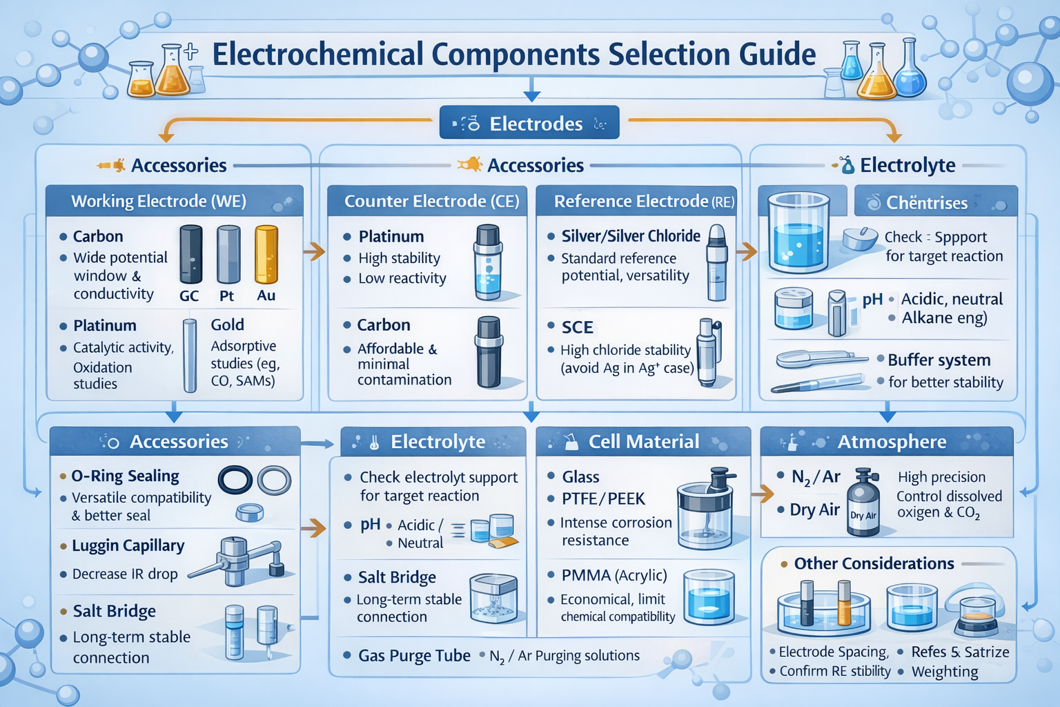
7. Practical Guide to Selecting Electrochemical Components
There is no universal “optimal” electrochemical setup. Suitability depends on your specific experimental question. A configuration that ignores the experiment objective can be expensive and complex yet still produce meaningless data.
7.1 Mechanism and Kinetics Studies
Focus: whether the actual WE potential is accurately controlled and whether results are comparable across experiments.
Recommendation: standard three-electrode configuration.
- WE: glassy carbon / Pt / Au (highly inert options)
- RE: Ag/AgCl or SCE, placed close to WE
- CE: Pt wire or Pt mesh with area significantly larger than WE
- Cell: mechanically stable geometry (glass or PTFE)
Pros: low background interference and high reproducibility.
Trade-off: more careful setup and lower throughput (often acceptable for fundamental research).
7.2 Sensor Development and Rapid Screening
Focus: sample-to-sample comparison under identical conditions, efficiency, and batch testing.
Recommendation: more integrated electrodes/cell structures (e.g., screen-printed electrodes, modular units).
Features include fixed geometry and relatively good repeatability with low per-test cost. Precision may be slightly compromised but the error is controllable. As long as comparison conditions are consistent, exchanging a bit of precision for efficiency is rational.
7.3 Battery, Electrocatalysis, or Corrosion Tests
Focus: high current, long duration, and closer-to-real operating conditions—system stability and durability first.
- Choose two- or three-electrode based on the objective
- Use actual device materials as WE (electrodes/metal substrates)
- Select CE with large area and low polarization
- Use robust sealing and corrosion-resistant materials
Here, the “polish” of a single dataset is not the top priority—long-term stability is.
7.4 Performance vs. Cost: A Realistic Strategy
Over-simplification early on often yields unreliable data; continuing to use “research-grade high configuration” later may only increase cost. A more realistic strategy is:
- When mechanisms are unclear, use a more rigorous setup to see the problem clearly.
- Once rules are established, simplify to improve throughput.
The goal is not to look professional—it is to be “just sufficient” to answer the current question.
8. Experimental Setup and Operational Notes
8.1 Installation Workflow (General Open Cell)
Assembly is typically performed from bottom to top: insert WE, RE, CE, and gas tubing into the corresponding ports on the cap; confirm insertion depth and correct positioning; align and tighten the cap to the cell body uniformly to ensure proper sealing; finally connect the gas line and complete the installation.
8.2 Prevent Contact Resistance and Intermittent Connection
Ensure both mechanical and electrical contact quality: avoid tilted insertion, ensure conductive parts fully contact to reduce resistance, tighten the cap evenly to prevent micro-movements that create noise and drift. Gas lines should be secure and leak-free to avoid bubble disturbance and pressure changes affecting contacts.
8.3 Quick Data Quality Self-Check
High-quality data typically show good repeatability, smooth baselines, and physically reasonable trends with condition changes. High overlap of repeated curves under identical conditions is the most direct indicator. If baseline is unstable, low-frequency noise increases, or peaks/parameters fluctuate without pattern, suspect poor contact, electrode position drift, excessive Rs, or unstable environment. Vary scan rate, current density, or electrode spacing and verify that responses follow basic physical/chemical rules; if not, return to system setup and workflow checks.
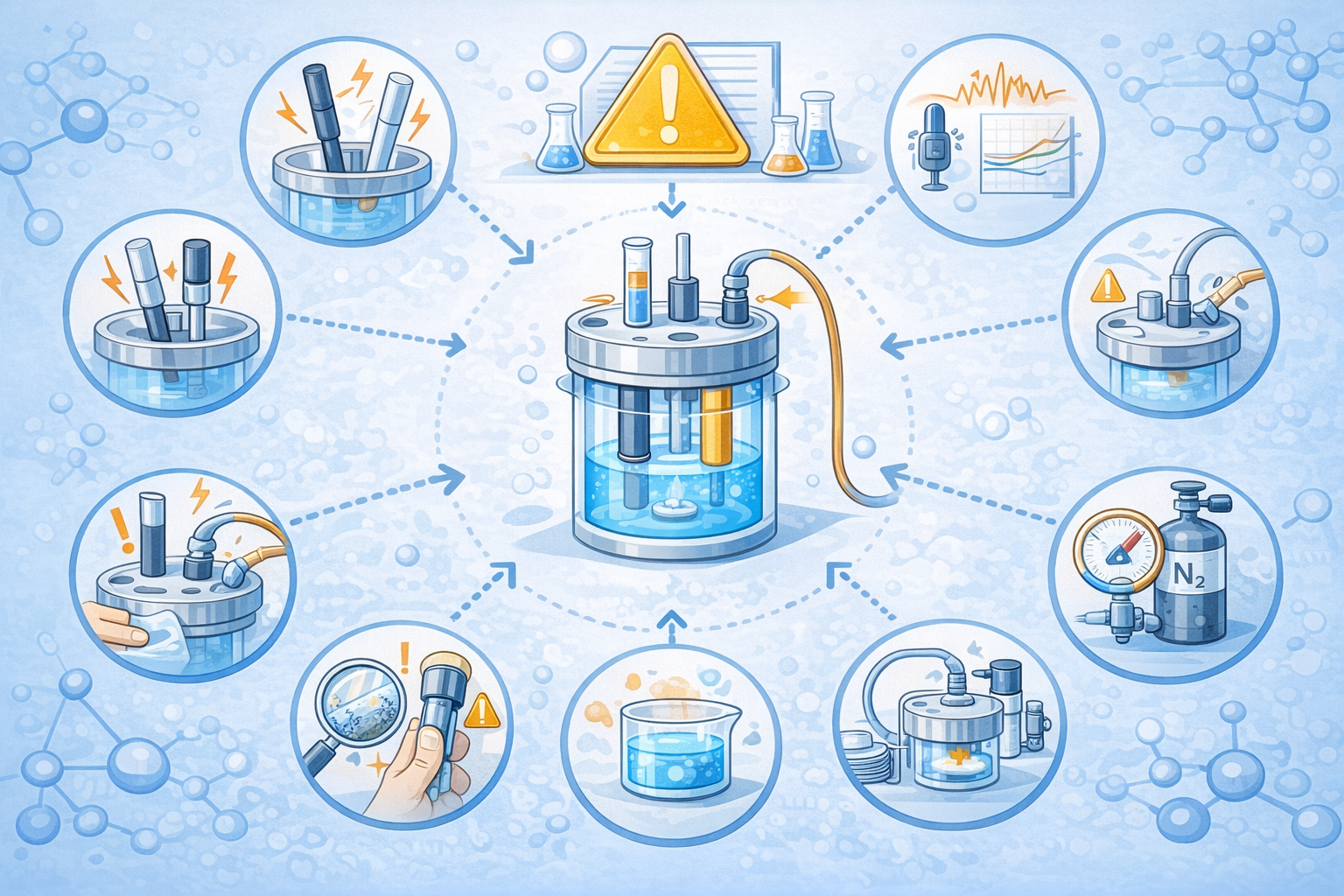
9. Common Mistakes and Debugging Strategy (Outside-In, Simple-to-Complex)
Abnormal electrochemical data are often not material issues but systematic errors caused by setup or operational details.
- RE wired incorrectly as CE
- RE positioned too far from WE
- Mixing different reference electrodes without potential conversion
- Insufficient polishing leaves contamination
- Over-polishing changes surface state
- Different experiments use different pretreatment protocols
- Electrolyte concentration preparation error
- Insufficient degassing
- Significant temperature fluctuations
10. Conclusion + Recommended Reading
Reliable electrochemical data are not determined by materials alone. They emerge from the combined effects of system design, component selection, operational details, and environmental control. From electrode spacing, solution resistance, and iR drop to material compatibility, component combination strategies, and common debugging workflows, seemingly minor parameters can amplify into major differences in final datasets. High-quality electrochemical experiments rely not only on instruments and materials, but also on a rigorous understanding of system logic and persistent refinement of details. Only when the setup is合理, variables are controlled, and procedures are standardized can results become reproducible, interpretable, and comparable across experiments.
- Screen-Printed Electrodes (SPE): structure, usage characteristics, and rapid analytical applications
- Electrochemical Impedance Spectroscopy (EIS): acquisition, equivalent circuit modeling, and common misinterpretations
- Multi-electrode systems and error sources: potential control, iR compensation, and geometric effects