


Electrochemical System Design: Electrodes, Electrolyte, Cell, and Troubleshooting
Electrochemical Experiments Are Engineering Systems
What you measure is not only the material — but the system built around it.
In electrochemical experiments, the most frustrating issue is often not that the material is “not good enough,” but that the same batch of material, the same workstation, and even the same operator can produce completely different curves on different days — CV peak positions drift, the low-frequency tail in EIS becomes longer, the onset potential jumps, and reproducibility is poor.
Many people immediately think “the material has a problem” or “there was an operational mistake.” But more often, what you measure is not the intrinsic performance of the material itself, but the combined behavior of the material under a specific electrode structure, electrolyte environment, cell geometry, and experimental condition.

An electrochemical experiment is not a single-variable test. It is closer to an engineered system. The material and surface state of the working electrode determine whether the interfacial reaction can be stable and repeatable; the stability and positioning of the reference electrode determine whether the potential is accurate; the area and material of the counter electrode influence current flow; the solvent and supporting salt in the electrolyte affect solution resistance (Rs) and ion migration; and the cell structure and electrode spacing directly influence mass transport pathways and iR drop.
Therefore, this guide approaches electrochemical experiment design from an engineering perspective — not only explaining what to use, but why to use it, and how to truly control experimental boundary conditions.
We will begin with the electrode system (WE/RE/CE), then clarify how the electrolyte matches the potential window, compare the measurement logic between two-electrode and three-electrode setups, and analyze how different cell types (open, sealed, H-type, flow-type) influence solution resistance (Rs), mass transport, and product pathways.
Finally, we will provide a structured troubleshooting framework to help you, when facing CV drift, peak shifts, EIS artifacts, or poor reproducibility, quickly determine whether the issue originates from the material or from the system itself.
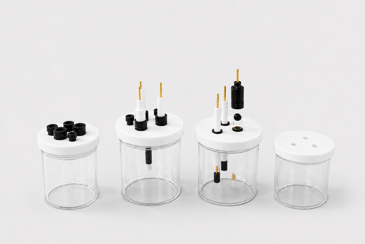
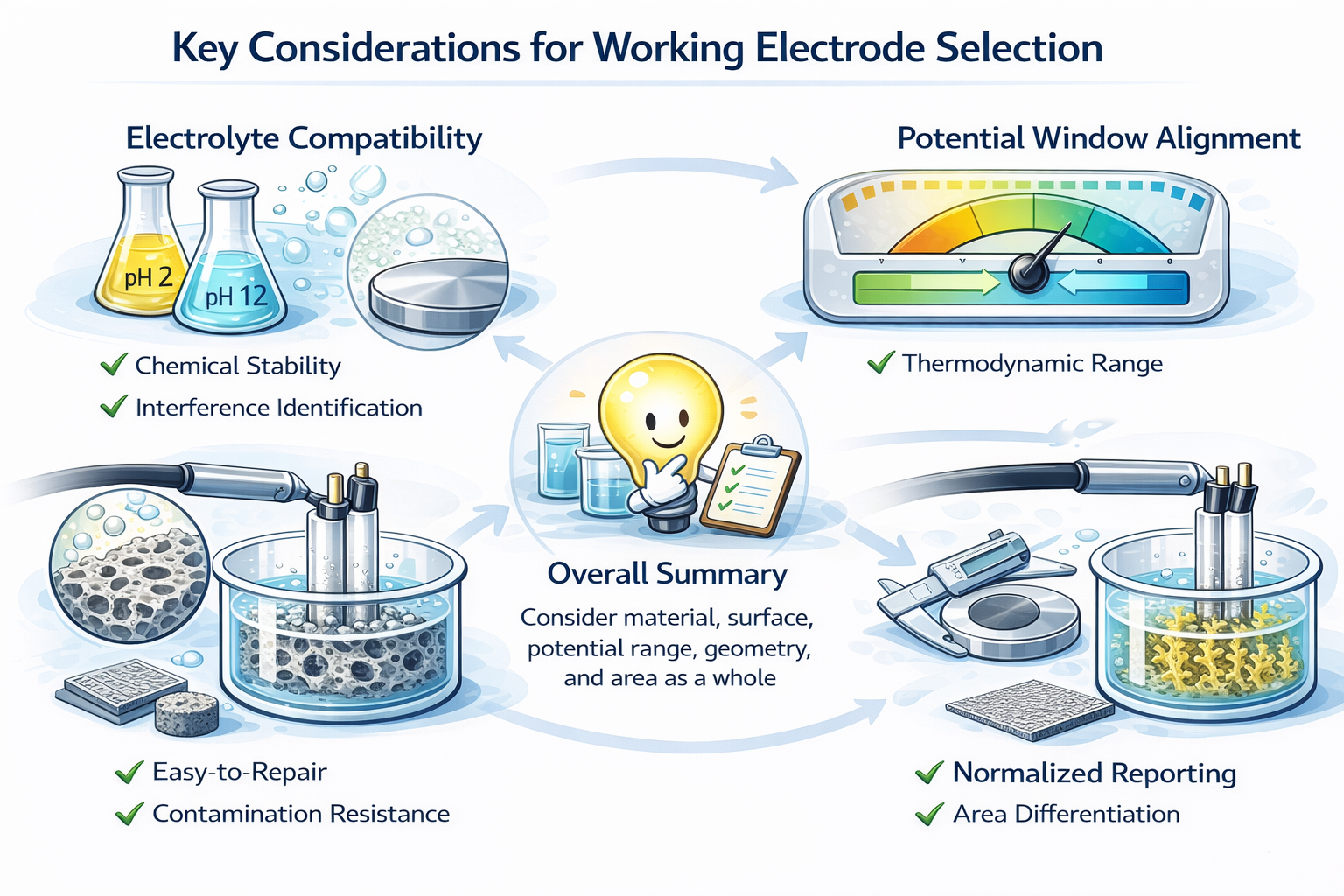
How to Choose a Working Electrode (WE)
The working electrode is where electrochemical reactions truly happen. To measure the material itself, you must first define the boundary conditions of the working electrode.
The Working Electrode (WE) is where the reaction actually takes place in an electrochemical system. Electron transfer, adsorption and desorption, film formation, dissolution, catalysis, and related processes all occur at the electrode–electrolyte interface.
In practical design, at least five questions must be considered together:
- Is the material truly inert, or will it introduce additional catalytic interference?
- In the current electrolyte, is the stable potential window sufficient?
- Is the surface state controllable and repeatable, with a standardized procedure?
- Is the area clearly defined (geometric area vs effective area)?
- Does the geometry match the current scale and mass-transport conditions (disk, sheet, mesh, foam, coating, etc.)?
1) Material Selection
The key of material selection is never “which one is more advanced,” but three things:
- Whether it directly participates in the reaction, or introduces additional catalytic interference
- Whether it remains stable in the target potential range
- Whether the background current and repeatability meet the experimental goal
If the material itself can be oxidized, reduced, or strongly catalyzes side reactions, then what you measure is no longer the sample behavior, but the influence of the electrode material itself.
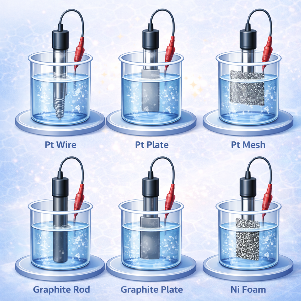
Comparison of common working electrode materials
Different materials do not have an “absolute best.” The only question is whether they match the experimental objective.
| Material | Key Advantages | Limitations | Typical Use |
|---|---|---|---|
| Platinum (Pt) | High conductivity, chemically stable, common standard | Expensive; strong catalytic activity may interfere | Catalysis, water electrolysis / oxygen reduction, electrochemical research |
| Gold (Au) | Stable surface, suitable for surface chemistry | Expensive; easy to oxidize at high potentials | Surface electrochemistry, sensors |
| Glassy Carbon | Inert, low background current, wide potential window | Brittle; requires polishing | CV, EIS, analysis |
| Graphite | Low cost, good conductivity, diverse forms | Variable structure, poor reproducibility | Batteries, electrolysis |
| Carbon Paste | Easy to prepare, tunable | Poor mechanical stability; suitable for organic solvents | Sensors, analytical electrochemistry |
| Mercury (Hg) | Excellent cathodic window, renewable surface | Toxic; limited anodic range | Polarography, trace analysis |
| Nickel (Ni) | Active in alkaline systems, low cost | Oxidation/activation; not inert | HER, alkaline battery research |
| Copper (Cu) | High conductivity, low cost | Easily oxidized | CO₂ reduction, battery materials |
| Stainless Steel | Reliable; strong industrial relevance | Non-uniform surface; poor reproducibility | Corrosion, industrial electrochemistry |
Quick selection suggestions (engineering judgment)
Different experimental objectives impose completely different requirements on the working electrode. Instead of asking “Which material is better?”, first ask: what exactly is your experiment trying to validate?
If the goal is mechanism analysis, potential window determination, or kinetics study, prioritize materials with low background current and surfaces that can be standardized, such as Glassy Carbon or Au. They are more likely to produce clean, repeatable data.
High specific surface area and strong current-carrying capacity are needed. Options include Pt mesh, Ni foam, carbon cloth, or carbon paper. In this case, geometry and mass transport must be fixed, otherwise the data will strongly depend on the system.
Prefer graphite or other carbon materials. If necessary, use isolation structures to avoid metal dissolution or cross-contamination.
Prefer Glassy Carbon, Pt, or Au, while strictly controlling moisture and oxygen content and ensuring potential-window matching.
2) Surface Structure
A working electrode is not only “what material,” but more importantly “what surface state.” The reason is simple: the reaction truly occurs at the interface, and the interface structure directly affects:
- Effective area
- Double-layer capacitance (Cdl)
- Charge transfer rate (Rct)
- Adsorption and film formation behavior
- Background current magnitude
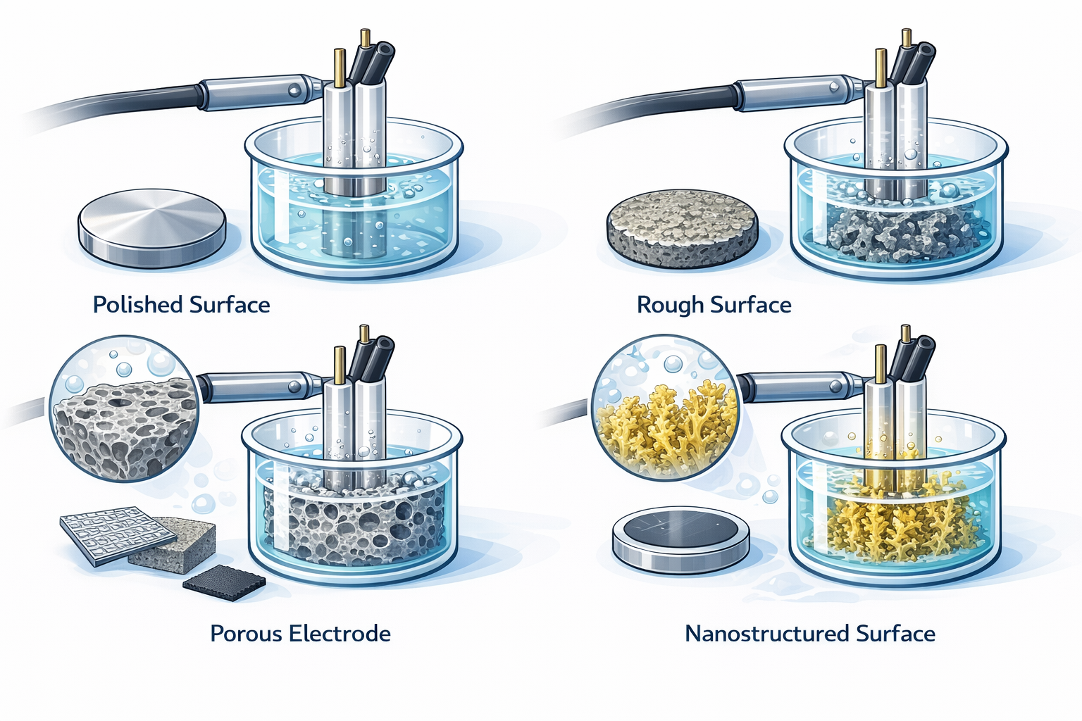
Common surface structures and their impact
Even for the same material, different surface states can produce completely different electrochemical results. Therefore, before comparing experimental data, you must confirm that you are comparing the “same surface condition.”
Advantages: good repeatability; low background current.
Typical use: mechanism studies, basic CV tests, potential window determination.
Typical electrodes: polished glassy carbon; polished Pt / Au sheets.
Advantages: increased effective area; higher current.
Risks: poorer repeatability; surface state is difficult to keep consistent over time.
Typical use: electrocatalysis; electrodeposition studies.
Advantages: high specific surface area; strong current-carrying capacity.
Risks: complex transport pathways; bubble accumulation; pore blockage; data strongly depends on geometry and fluid conditions.
Typical electrodes: Pt mesh; Ni foam; carbon cloth; carbon paper.
Advantages: abundant active sites; significantly improved performance.
Risks: weaker structural stability; reproducibility may be affected.
Typical use: advanced catalysis; sensing studies.
Advantages: controllable structure; better repeatability; suitable for quantitative comparison.
Risks: adhesion, thickness, and defects directly affect results.
Typical electrodes: sputtered metals; electrodeposited films.
Engineering experience summary (very important)
When “the same material produces completely different curves,” do not doubt the material first. Instead, check whether the surface state is consistent:
- Is the polishing grit the same?
- Is the cleaning procedure the same?
- Is an oxide film formed?
- Is there adsorbed contamination?
- Has the electrode been used before, and is the usage history different?
Many so-called “material differences” are essentially surface-state differences.
3) Geometric Area vs Effective Area
What is Geometric Area?
Geometric area is the area calculated directly from electrode dimensions such as diameter, length, exposed region, etc. It does not consider:
- Surface roughness
- Porosity
- Nanostructures
- Catalyst particles
It is typically used to:
- Calculate current density
- Standardize comparisons between experiments
- Serve as a unified reference in papers or reports
Simple understanding: geometric area is “how big it looks.”
What is Effective Area?
Effective area is the interfacial area that truly participates in the reaction. It can be affected by:
- Whether the surface is rough
- Whether there are pores
- Whether a catalyst is loaded
- Whether there are nanostructures
Effective area directly determines:
- Peak current magnitude
- Double-layer capacitance (Cdl)
- Charge transfer resistance (Rct)
- CV curve shape
- EIS fitting stability
You can understand it as: effective area is “the area where reaction truly happens.”
A very common but easily overlooked issue
In many experiments:
- What is reported is geometric area
- What actually matters is effective area
When the gap between them is large:
- Current density may be overestimated or underestimated
- Catalytic performance comparisons may be distorted
- Experiments become hard to reproduce
Quick judgment by experience
- Polished glassy carbon → effective area ≈ geometric area
- Rough electrode → effective area slightly larger
- Porous electrodes / metal foams / carbon cloth → effective area can be several to tens of times larger
- Catalyst-loaded electrodes → effective area depends on particle dispersion and loading amount
Current density is determined by effective area, not geometric area.
Most common mistakes in experiments
- Comparing current density directly between flat electrodes and porous electrodes
- Not fixing immersion depth
- Comparing performance directly with different catalyst loading
- Drawing “better material” conclusions using electrodes with different areas
These problems look like material differences, but are actually caused by area not being unified.
Suggested practice
In your report or lab notes, at minimum, clearly state:
- Geometric area (A_geo)
- Source of effective area (roughness / porosity / catalyst)
- Electrode sealing method and exposed region
- Whether immersion depth is fixed
Only when this information is clear can your data be truly comparable.
5) Engineering Selection Logic (Follow This Order)
Choosing a working electrode is not that complicated. What easily causes problems is using the wrong order. Many people start by asking: “Which material is better?” But the correct order should be:
Step 1: What exactly do you want to measure?
Don’t rush to choose an electrode. Are you doing mechanism research? Running high current? Or testing a device-like setup?
If it is mechanism analysis, CV, or potential window determination (more fundamental research), prioritize electrodes that are highly inert, have low background current, and can be restored by polishing, such as glassy carbon, Au, or Pt disk electrodes.
If it is water electrolysis, high current, or engineering-condition simulation, then high specific surface area structures are needed, such as metal foams, metal meshes, carbon cloth, or carbon paper. But remember: geometry and mass transport must be fixed.
Step 2: Is it stable in your electrolyte?
An electrode material may work well in one system, but may start to decompose after changing pH or solvent. So ask:
- Will it be corroded?
- Will it be oxidized?
- Will it induce solvent decomposition?
If the material is not stable, the current you measure may not be from the target reaction at all.
Step 3: Does the potential window match?
The potential range of the target reaction must fall within the intersection of:
- The electrode stability window
- The electrolyte stability window
If the potential exceeds the window, the solvent may decompose first, not the reaction you want to study. Many cases of “poor performance” are simply caused by choosing the wrong potential range.
Step 4: Can the surface stay consistent?
Some electrodes look great in the first run, but become completely different in the second. When selecting an electrode, consider:
- Can it be restored by polishing?
- Can it be cleaned thoroughly?
- Will it be permanently contaminated by products?
If the surface state is different every time, the data cannot be consistent.
Step 5: Are area and geometry unified?
This is the most easily overlooked point. You may report geometric area, but what truly matters is effective area.
- Is immersion depth fixed?
- Is the sealing/exposed region consistent?
- Is loading amount unified?
If these are not unified, curve drift is almost inevitable.
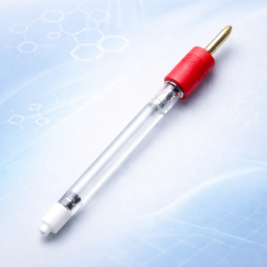
How to Choose a Reference Electrode (RE)
A reference electrode provides a stable and repeatable potential baseline. If the RE drifts, every “potential” you see will drift with it.
The reference electrode (RE) has only one job: to provide a stable, repeatable potential reference.
What you observe — CV peak positions, overpotential, EIS potential-related parameters, and onset potential shifts — are all results relative to the reference electrode. If the RE drifts, all reported potentials drift with it. Many cases of “unstable materials” are actually the reference electrode changing.
In a three-electrode setup: WE → reaction happens; CE → provides current; RE → defines potential. The RE carries almost no current and does not participate in the reaction. It is simply a “potential ruler.” If the ruler is wrong, every number becomes wrong.
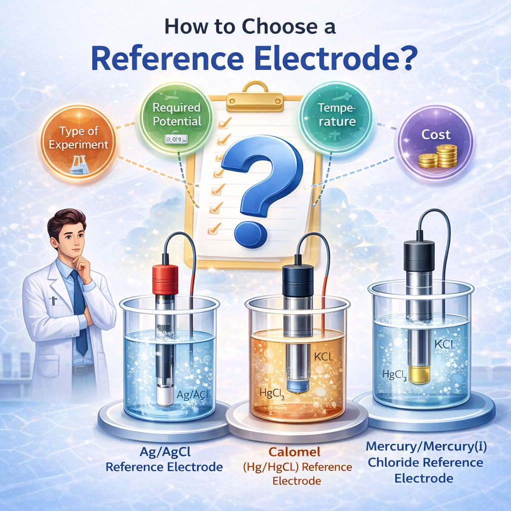
How to choose a reference electrode (follow this order)
Choosing the wrong RE is one of the most hidden — and most fatal — mistakes in electrochemical experiments. Do not start by asking “which one is best.” Start by asking: which one truly matches your system?
① Is your system aqueous or non-aqueous?
This is the first step, and also the most important step.
Ag/AgCl · SCE (calomel) · Hg/HgO · Hg/Hg₂SO₄ · RHE
Ag/Ag⁺ · Li/Li⁺ (battery systems)
- The internal filling solution must remain stable.
- The solvent should match the tested system as closely as possible.
- Do not bring an aqueous reference electrode into an organic system.
② What is your pH range?
Under different pH conditions, stable reference systems differ.
- Alkaline systems → Hg/HgO
- Acidic systems → Hg/Hg₂SO₄
- Neutral systems → Ag/AgCl or SCE
- Large pH variation or complex systems → RHE is often safer
When pH does not match, the potential may not “error out” immediately — it often drifts slowly, making you think it is a material problem.
③ Do you have special environments?
- Brine or high ionic strength: RHE is often more stable; Ag/AgCl may be affected by Cl⁻.
- HF environments: prioritize RHE; most traditional REs can be corroded by HF.
- High-temperature experiments: Ag/AgCl and SCE are primarily designed for room temperature; higher temperature can shift potential significantly — be cautious.
④ Is your system sensitive to contamination?
If you are working with:
- Biological systems
- Trace analysis
- CO₂RR
- Surface catalysis
then contamination risk must be considered:
- Ag/AgCl → may leak Cl⁻
- Calomel / Hg-based → contains mercury
- RHE → relatively cleaner
Contamination often does not cause immediate failure — it makes the data slowly become “off.”
⑤ Are you running EIS?
EIS is very sensitive to the reference electrode state. If you see:
- High-frequency artifacts
- Abnormal fitting
- Abnormal phase angle
many times the issue is not the sample, but the RE internal resistance or unstable contact. Prefer references with:
- Low internal resistance
- Stable state
- Reliable contact
Maintenance & troubleshooting (more important than selection)
When you see:
- CV drift
- Peak position shifts
- EIS high-frequency abnormalities
- Sudden increase in noise
check the RE first, not the material.
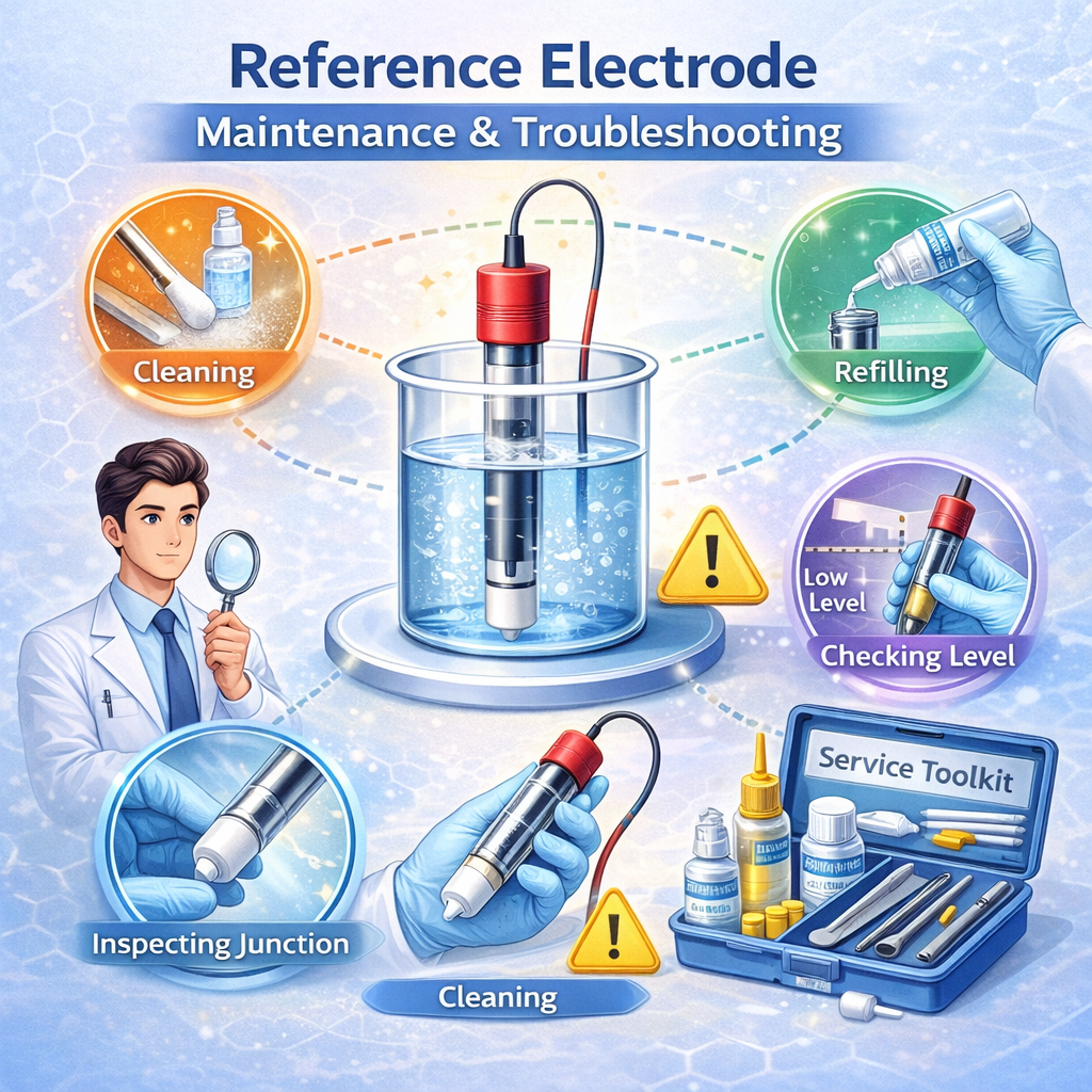
Suggested troubleshooting order
Bubbles inside a traditional RE can change contact, introduce noise, and cause unstable potential. Gentle shaking or flipping often removes them.
Check: corrosion, poor contact, salt deposition. During storage, avoid letting electrolyte contact the metal part.
A contaminated or blocked frit can cause potential drift, fluctuations, or potentiostat oscillation. Note: Ag/AgCl in systems containing ClO₄⁻ may form deposits that clog the frit.
Check RE internal resistance, frit condition, and contact stability first. Do not blame the sample at the beginning.
The reference electrode is not a “supporting role.” It determines whether the potential is reliable, whether data are comparable, and whether experiments are reproducible. Many “material problems” are actually RE drift.
The most practical summary
The selection logic of an RE is only one line: system matching matters more than “a more advanced model.”
Electrolyte · pH · temperature · contamination sensitivity · EIS needs — if these match, the reference electrode will not become your hidden variable.
How to Choose a Counter Electrode (CE)
The counter electrode closes the current loop with the working electrode. Its job is simple: carry the current smoothly, so the reaction can happen stably on the WE.
The counter electrode (also called the auxiliary electrode) forms a complete current loop together with the working electrode (WE). Its role is straightforward: carry the current, so the reaction can occur stably on the WE.

The CE is not your research object — you do not care what reaction happens on it. What you truly care about is: it should not interfere with your control of the WE.
If the CE area is too small, or the material is not suitable, strong polarization can appear. Then part of the applied voltage is “consumed” on the CE instead of acting on the WE. The result is: you think the potential is correct, but the system has already shifted.
The effective area of the CE should be at least 5–10× the WE area.
The logic is direct:
- Larger area → lower current density per area
- Lower current density → lower polarization
- Lower polarization → more stable WE potential
- More stable potential → less noise and less error
In other words: if the CE is large enough, the system becomes “quieter.”
What happens if the CE is too small?
- Large overpotential appears on the CE
- Potential distribution is pulled off
- iR drop increases
- Curves start to drift
- Repeatability decreases
In low-current tests these issues may be subtle. But in high-current experiments (water electrolysis, electrocatalysis, flow cells), the impact becomes much larger. Many cases of “unstable data” are simply because the CE is too small.
Common counter electrode materials
stable, and large enough.
Limitations: high cost; long runs may cause trace dissolution and redeposition onto the WE.
Typical use: CV, EIS; basic electrochemical tests; common “standard” CE.
Typical use: high-current experiments; long-duration runs; common substitute for Pt.
Typical use: water electrolysis; electrocatalysis experiments.
How to choose a CE with an engineering mindset
When selecting a CE, focus on four things.
① Current scale
- Low current (CV, EIS) → Pt wire / graphite plate is usually enough
- High current (electrolysis, electrocatalysis) → large-area structures are required (Pt mesh, graphite rod, Ni foam)
If the CE cannot carry the current, the voltage will be “eaten” by the CE.
② Area ratio
- CE ≥ 5–10× WE
If area is insufficient, most problems will follow.
③ Material–system matching
Simple judgment:
- Strong acid / strongly oxidative → prioritize Pt
- Alkaline systems → graphite / Ni / Pt
- Non-aqueous systems → graphite or Pt
- Cl⁻ or corrosive environments → avoid easily dissolved metals
If the material is not stable, the CE itself becomes a reaction source.
④ Avoid catalytic interference and contamination
Especially important in mechanism studies or contamination-sensitive systems:
- Pt may participate in HER / OER
- Long runs may cause trace dissolution
- Metal may deposit on the WE and change its behavior
If the system is contamination-sensitive:
- Prefer graphite-based CE
- Or use an H-type cell to isolate compartments
Otherwise, what you measure may no longer be the original material.
CE position also matters
The counter electrode is not “the same anywhere.” Its position affects:
- Electric field distribution
- Solution resistance (Rs)
- iR drop
- Mass-transport pathways
Keep a reasonable distance from the WE · do not block mass transport · do not face the RE directly · fix the position and avoid movement during experiments. If geometry changes, the system changes.
Common mistakes
When experiments look abnormal, the CE is often ignored. Common issues include:
- CE area too small → severe polarization
- CE too close to WE → concentrated electric field
- CE conflicts with RE position → distorted potential
- Pt CE in long runs → metal contamination
- Porous CE not fixed → geometry changes cause Rs drift
If the WE seems fine, check the CE first.
A common misunderstanding
Sometimes people see the CE potential “looks stable” and try to use it as a reference. This is wrong. The CE potential is not a fixed thermodynamic potential — it changes with current and reaction conditions. It may only “look stable” under some low-current conditions. The CE can never replace the RE.
The CE has only one task: do not become the limiting factor of the system. It does not need to “perform well.” It only needs to be large enough, low-polarization, stable, and non-contaminating — so you can truly control the potential on the WE.
Otherwise, what you measure is not only material behavior — it also includes system errors introduced by the CE.
Electrolyte, 2-Electrode vs 3-Electrode Setup, and Cell Selection
The electrode defines where the reaction happens. The electrolyte defines how it happens. The cell defines the boundary conditions.
3) Electrolyte: the environment where electrochemical reactions truly happen
In electrochemical experiments, the electrolyte is not simply a “background” that makes the solution conductive. It is the environment where the reaction happens. Many times, we think we are measuring a material, but what we actually measure is how that material behaves under a certain electrolyte condition. The electrolyte affects ion migration, interfacial state, and reaction pathways, so the same electrode can give completely different results after changing the electrolyte.
An electrolyte system is not only solvent and supporting salt. It also includes reactants, pH, atmosphere, and temperature. Together, they determine whether the potential is stable, where the current comes from, and whether the data can be reproduced.
The truly usable potential range is the intersection of the stability windows of the solvent, the electrolyte, and the electrode. Once you exceed it, what happens first is often solvent or electrode decomposition, not the target reaction.
The electrode decides where the reaction happens. The electrolyte decides how the reaction happens. Only when the electrolyte system is well controlled can the true performance of the material be measured.
4) Two-electrode vs three-electrode setups
This is not simply “one more electrode” — it is a completely different measurement logic. The two-electrode setup is common in batteries, supercapacitors, or industrial electrolysis devices. It includes only the working electrode (WE) and the counter electrode (CE).
What you measure is the total voltage of the whole system — the combined result of both electrodes. It has a simple structure and is closer to real device operation, so it is suitable for battery or device performance evaluation. But its limitation is also clear: you cannot precisely know the true potential of the working electrode, because the WE always changes together with the CE.
In other words, a two-electrode setup is more like looking at “overall performance,” rather than the independent behavior of a single electrode.
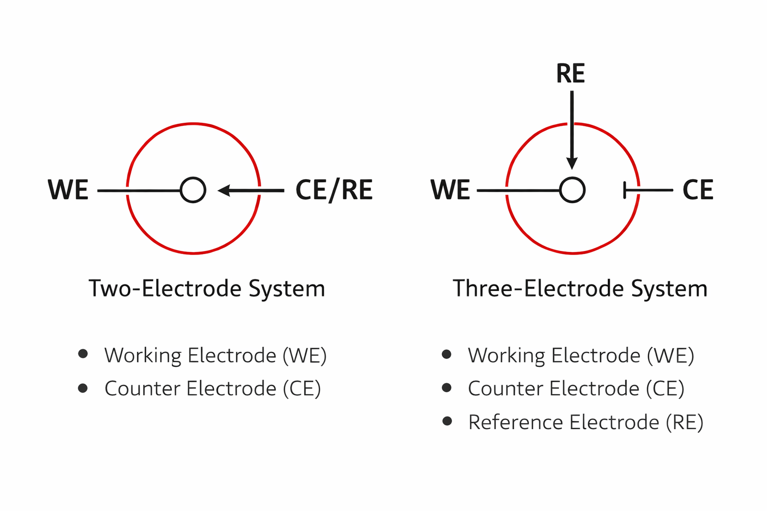
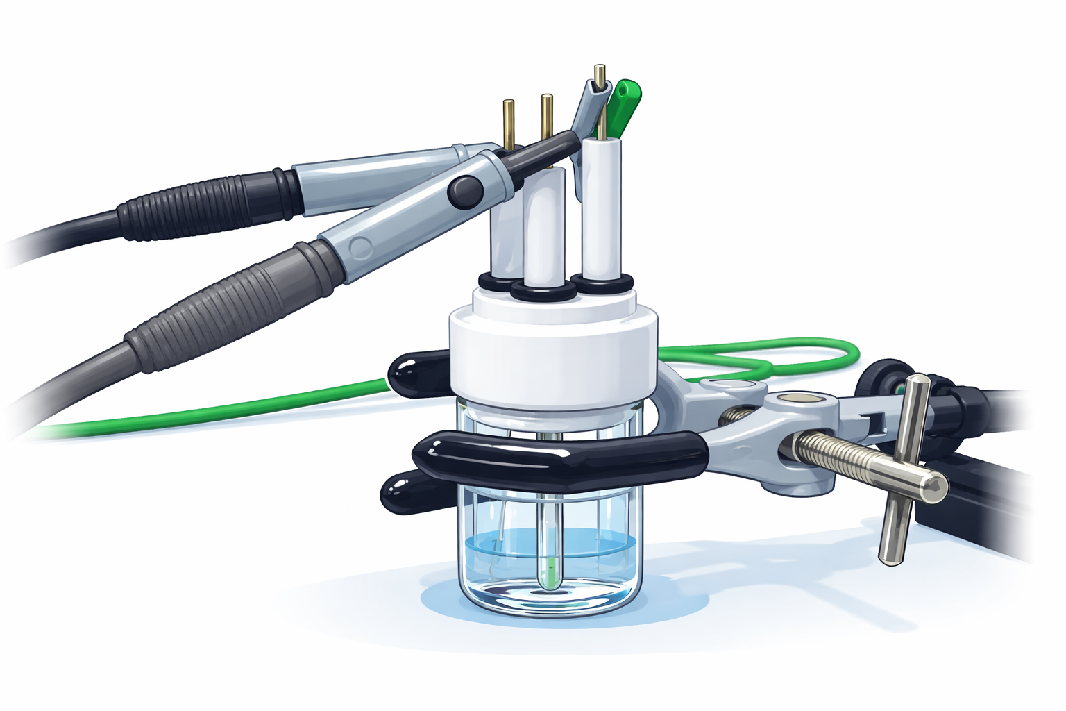
The three-electrode setup adds a reference electrode (RE). In this structure, the potentiostat controls the potential of the WE relative to the RE, while current flows between the WE and the CE. The RE does not participate in the current; it only provides a stable potential reference.
This separates “potential control” from the “current path,” so the reaction on the WE can be studied independently and precisely. Also, because the RE carries almost no current, the iR drop caused by solution resistance is reduced, the data are more stable, and repeatability is better.
Therefore, in laboratories, as long as your goal is mechanism study, material evaluation, or accurate potential measurement, the three-electrode setup is basically the standard configuration.
Common use cases
- CV: analyze redox processes and reaction mechanisms
- EIS: study charge transfer, capacitance, and diffusion behavior at the interface
- Electrocatalysis (HER, OER, CO₂RR): evaluate the true activity of catalysts on the WE
- Corrosion: measure OCP and polarization curves to assess stability
- Battery/supercapacitor fundamental studies: analyze cathode or anode processes separately, instead of only the full-cell result
To study the true behavior of a single electrode, use three electrodes. To evaluate the overall performance of a device, use two electrodes.
5) How to choose an electrochemical cell
An electrochemical cell is not just “a glass cup that holds electrolyte.” It defines the physical boundary conditions of the experiment: electrode spacing, electrolyte volume, whether there is convection, and where products go. These factors directly affect Rs, mass transport, and iR drop. So it is not surprising that the same material can produce completely different curves in a different cell.
From an engineering viewpoint, a cell defines three things:
- How the electric field is distributed: change electrode spacing → Rs / iR drop changes
- How mass moves: static diffusion vs convection supply → current response changes
- Whether products interfere back: crossover or secondary reactions reshape the curve
When you change the cell, you change the system boundary — so the data naturally change.
Fast selection logic (use this first to save time)
- Sensitive to air/moisture → sealed cell
- Need to separate anode/cathode products → H-type cell
- High current density or continuous reactions → flow cell
- Only CV/EIS, quick screening, short tests → open cell
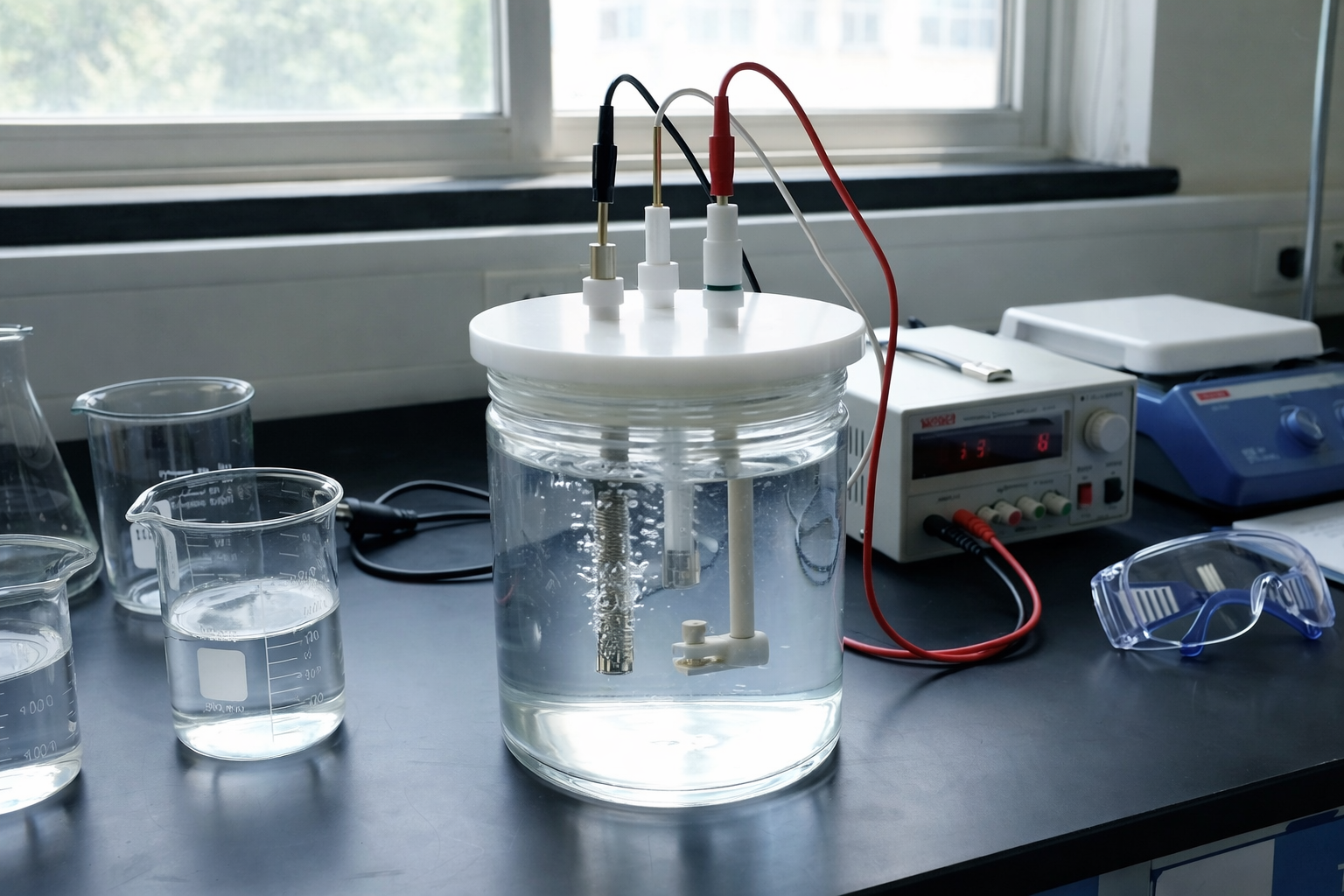
1) Open cell
The most common and most convenient option: open top, electrodes can be inserted and replaced easily. It is very convenient for CV, EIS, and routine electrocatalysis, and is suitable for material screening and general characterization.
But its boundary conditions are not fully “locked”: electrode spacing depends on placement and Rs is often larger; O₂/CO₂/moisture in air may introduce side reactions; evaporation and temperature fluctuations are also more obvious. Suitable for quick tests, comparisons, and short runs — not suitable for strict environment control or long stable operation.
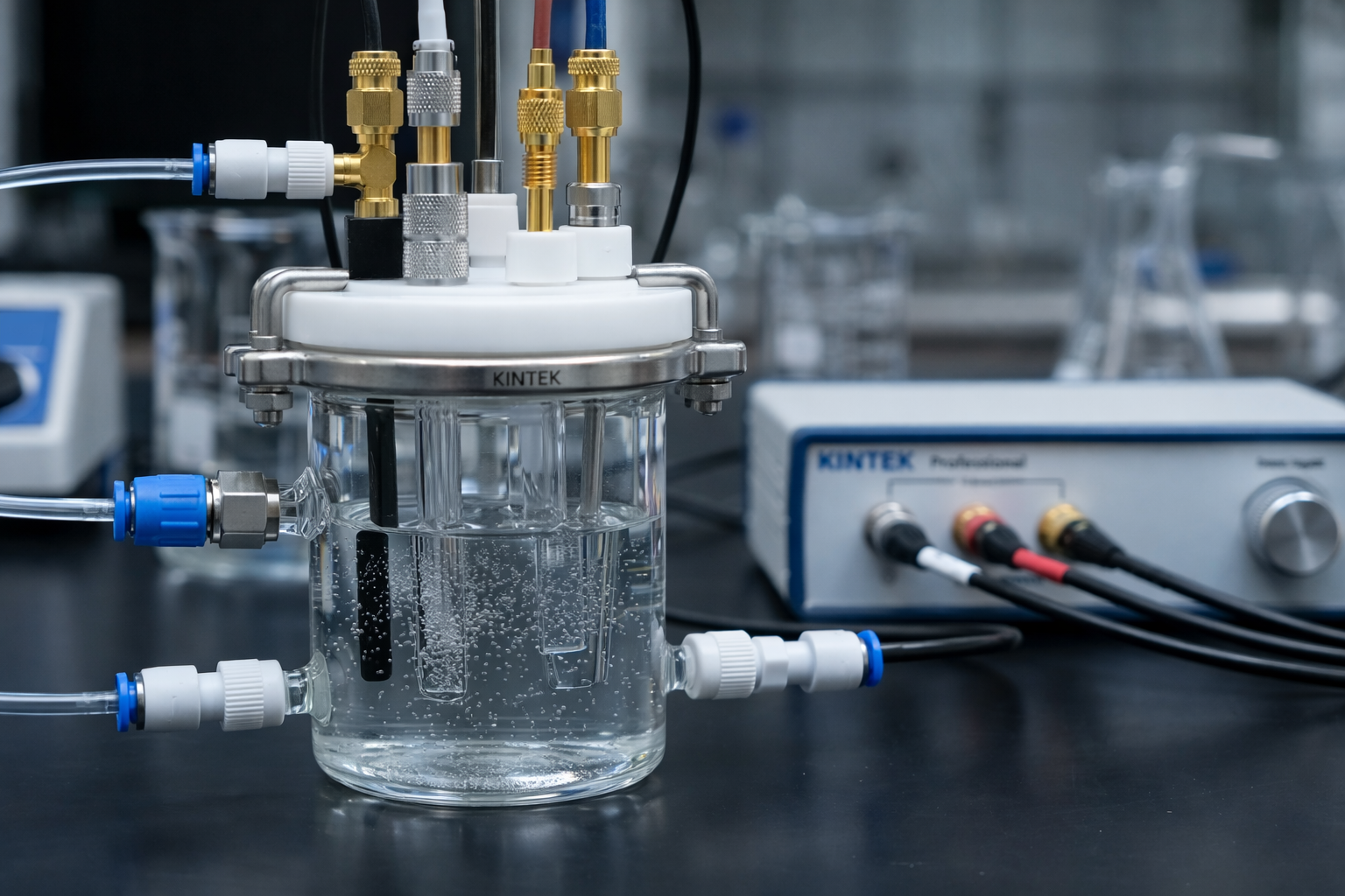
2) Sealed cell
The core idea is to “lock” conditions: isolate air and moisture, reduce evaporation, oxygen side reactions, and electrolyte composition drift, so repeatability is significantly improved.
Especially suitable for non-aqueous electrolytes, organic electrochemistry, battery-related systems, and gas-sensitive systems. Sealed designs also make it easier to fix electrode positions and spacing, leading to smaller Rs variation and more stable potentiostatic/galvanostatic control.
Open cells are for convenience; sealed cells are for stability.
3) H-type cell
An H-type cell separates the anode and cathode compartments using a membrane/diaphragm: ions can pass, but products from the two sides are less likely to mix directly.
The value is not “more complicated,” but clearer mechanism: it reduces crossover and secondary reactions, allows separate sampling and quantitative product analysis, improves selectivity evaluation, and makes it easier to identify which side the reaction truly occurs on. Common for water electrolysis, CO₂ reduction, nitrogen reduction, and other experiments where products and mechanism matter.
4) Flow cell
A flow cell uses a pump to continuously drive electrolyte through the reaction zone: reactants are continuously supplied and products are removed, mass transport is stronger, concentration polarization is smaller, current density can be much higher, and it is closer to engineering operating conditions.
Common for high-current electrocatalysis, electrochemical synthesis, fuel cells, and continuous reaction systems. In one sentence: it is closer to “engineering operation simulation,” not only static characterization.
Common “illusions” caused by the wrong cell
When the cell does not match the experiment, the most common issues are:
- Rs increases and iR drop becomes stronger
- Product crossover and secondary reactions
- System drift, instability, and unreproducible data
Many times it looks like the material becomes worse — but in fact, only the boundary conditions changed.
System Matching Principles
Electrodes, electrolyte, cell, geometry, and test conditions form a strongly coupled system. One mismatch can shift the entire result.
Electrodes, electrolyte, electrochemical cell, geometric arrangement, and test conditions are a strongly coupled system. If any one part is chosen incorrectly, it can change potential distribution, mass-transport paths, and interfacial states, causing your data to deviate from the true behavior.
What you measure is never “the material itself,” but the material’s response inside a specific system.
1) The system is coupled, not assembled
The electrolyte can change reaction pathways; electrode geometry can change the electric field and Rs; the cell structure can change mass transport and product migration; temperature and atmosphere can affect interfacial stability.
This is why changing only one variable (only changing material / only changing electrolyte) often does not help, because other parts are still changing the experimental boundary conditions.
2) Many “material problems” are actually system mismatch
- Electrolyte mismatch → reaction is suppressed, low current, abnormal onset potential
- Unstable WE surface → poor repeatability, curve drift
- RE drift → overall CV shift, peak-position changes
- Unreasonable spacing → larger Rs, obvious iR drop
- Cell mismatch → crossover reactions, severe concentration polarization
It may look like the material is “worse,” but in many cases the system boundary conditions have changed.
3) “Matching” is more important than “optimizing”
The material must match the mechanism. The electrolyte must match the potential window and pathway. The RE must match the system type. The CE must match the current scale. The cell and geometry must match mass transport and Rs control.
Only when these parts work together can experiments become repeatable and comparable.
4) Engineering conclusion
The root cause of many cases of “low activity,” “curve drift,” and “poor reproducibility” is not the material, but system mismatch. When the system is designed correctly, the data can truly reflect intrinsic material behavior.
Electrochemical Experiment Design Workflow
Follow this order and you can avoid 80% of common pitfalls.
Electrochemical experiments do not start with “choosing a material.” They start with defining the objective. If you follow the workflow below in sequence, you will find that many so-called “material problems” simply do not appear.
Step 1 | Define the experimental objective first
State clearly in one sentence: Are you measuring mechanism (kinetics / potential dependence), performance (current density / stability), products (selectivity / Faradaic efficiency), or a device (battery / supercapacitor, two-electrode)?
At the same time, write down these four key conditions:
- System type: aqueous / non-aqueous / solid-state
- Gas involvement: O₂ / CO₂ / N₂ / others
- Expected current level: µA, mA, >100 mA
- Long-term operation or product quantification required?
Objective + system type + current scale + whether long-term / product quantification is required.
Step 2 | Define the Working Electrode (WE)
Choosing a WE is not just “selecting a material.” It means fixing these four aspects at once:
- Material: Pt / Au / glassy carbon / graphite / metal foam / carbon cloth …
- Geometry: disk / plate / mesh / foam / coating
- Surface state: polished / porous / nanostructured / thin film
- Area definition: geometric vs effective (state clearly which one is used for current density)
Quick selection logic:
- Mechanism research → inert, low background, reproducible surface (glassy carbon / Au / Pt)
- High current / engineering test → high surface area support (mesh / foam / carbon paper), and fix loading & structure
WE material + geometry + surface treatment procedure + area definition.
Step 3 | Design the electrolyte system
The electrolyte is not just “salt water.” It is the reaction environment. Define these four in order:
- Solvent: determines potential window and stability
- Supporting electrolyte: determines conductivity and Rs
- Active species: determines reaction pathway and current source
- pH / water content / atmosphere: determines interface state and mechanism
Practical reminders:
- Non-aqueous systems → strictly control water and oxygen
- Gas-sensitive reactions → control gas flow rate, purity, bubbling method
- High current → reduce Rs first, otherwise iR drop will dominate results
Electrolyte composition (solvent / salt / concentration / active species / pH) + environmental conditions.
Step 4 | Select the Reference Electrode (RE)
Core requirements: stable potential + compatibility with the system.
- Aqueous systems → Ag/AgCl, SCE
- Non-aqueous systems → Ag/Ag⁺ (internal solution must match solvent)
- Wide pH range or contamination-sensitive → RHE or calibratable systems
Also fix these three:
- Distance between RE and WE (closer → smaller iR error)
- Whether to use a Luggin capillary (to bring sensing point near WE)
- Drift control strategy (temperature / time / frit blockage; especially critical for EIS)
RE type + placement method (distance / Luggin) + drift control strategy.
Step 5 | Choose two-electrode or three-electrode
- Mechanism / kinetics / precise potential comparison → three-electrode
- Device performance / battery / supercapacitor → two-electrode
Three-electrode → study single-electrode behavior.
Two-electrode → evaluate whole-device/system performance.
Clearly define which entity your data belong to: single electrode or entire system.
Step 6 | Fix the electrochemical cell and geometry
Lock these boundary conditions and repeatability will immediately improve:
- Cell type: open / sealed / H-type / flow
- Electrode spacing (directly affects Rs and iR drop)
- Volume and stirring/convection (defines diffusion layer and concentration polarization)
- Product pathway (isolation / crossover)
- Gas management (bubbling method, flow rate, compartment sampling if quantifying products)
Quick mapping:
- Open cell → general characterization, short comparison
- Sealed cell → non-aqueous / long-term stability / controlled environment
- H-type cell → product isolation, mechanism & selectivity
- Flow cell → high current, engineering-like operation, continuous reaction
Cell type + geometric parameters (spacing / volume / stirring / gas conditions).
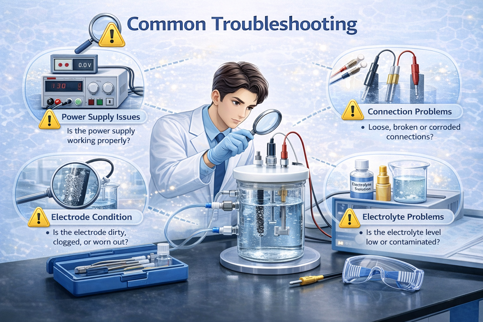
Common Issues & Troubleshooting
Diagnose the system first — not the material.
When electrochemical data become abnormal, the worst reaction is to immediately doubt the material. The effective approach is to troubleshoot according to system priority.
Reference → Resistance → Geometry → Interface → Environment
First confirm the potential reference, then check Rs and electrode positioning, then examine surface state and electrolyte condition, and only at the end consider temperature and atmosphere. Most problems are found in the first two steps.
1) CV Drift
If the entire curve shifts, peak positions move over time, or repeated scans do not overlap, the most common cause is not the material, but a changing system.
The first suspect should always be the reference electrode. If the RE potential drifts, the entire CV shifts with it. Frit contamination, internal solution change, bubbles, temperature fluctuation, or aging can all cause this.
The second common cause is electrolyte change. CO₂ absorption in alkaline media, water uptake in non-aqueous systems, metal-ion dissolution, or contamination can alter background current and peak shape. Repeating the test with fresh electrolyte often quickly reveals the issue.
Another frequently overlooked source is WE surface condition. Inconsistent polishing, oxidation, adsorption, or catalyst-layer change can gradually alter CV shape.
2) EIS Low-Frequency Tail Change
The low-frequency region of EIS reflects mass transport and interfacial processes. If the tail becomes significantly longer, the physical boundary of the system has likely changed.
Common causes include changes in solution resistance or electrode position. Electrolyte concentration, temperature, bubbles, immersion depth, electrode spacing, or even slight mechanical movement can alter the low-frequency response.
If the low-frequency tail continues to grow while Rct increases and Cdl changes, the interface itself may be evolving — film formation, contamination, pore blocking, or activity decay.
3) Peak Position Shift
The most common reason for peak shift is iR drop, not necessarily a change in reaction mechanism.
When Rs increases or current becomes larger, the difference between displayed potential and true interfacial potential increases. Low supporting electrolyte concentration, large electrode spacing, or reduced conductivity can all cause this.
Temperature is another often overlooked variable. It simultaneously affects conductivity, diffusion, and kinetics, shifting both peak potential and peak current.
If pH or reactant concentration changes, the peak shift may reflect real chemical-environment changes.
4) Poor Reproducibility
Poor reproducibility is almost never due to “instrument noise.” It usually means boundary conditions were not fixed.
The most typical issue is area inconsistency. Many experiments report geometric area, but effective area actually controls current. Small differences in immersion depth, polishing level, coating thickness, or clamping pressure can lead to large current and impedance differences.
Electrolyte variability is another common source: batch difference, preparation error, water uptake, CO₂ absorption, or solvent evaporation.
In open cells, electrode positioning is particularly critical. Slight differences in WE–RE–CE distance, stirring, or bubbling conditions change Rs and mass transport, and the curve changes accordingly.
Most “abnormal data” are system problems. Confirm the reference, resistance, and geometry first — and only then evaluate the material.
Pre-Experiment Checklist
30-second scan before turning on the potentiostat. Most abnormal data can be avoided before the experiment even starts.
① Define the Objective (Don’t insert electrodes first)
- Am I measuring mechanism / performance / product / device?
- System type: aqueous / non-aqueous / solid-state?
- Expected current level: µA / mA / >100 mA?
- Long-term operation or product quantification required?
② Working Electrode (Where reaction happens)
- Is the material matched to the reaction?
- Is surface treatment consistent (polishing / cleaning / loading)?
- Is geometric area clearly defined?
- Could effective area vary (rough / porous / catalyst layer)?
- Is immersion depth fixed?
③ Reference Electrode (Your potential ruler)
- Is the potential stable?
- Is the internal solution compatible with the system?
- Any bubbles inside?
- Is the frit clean and unblocked?
- Is the distance to WE fixed?
④ Counter Electrode (Don’t let it limit you)
- Is CE area ≥ 5–10× WE area?
- Is the material stable in the electrolyte?
- Any risk of catalytic interference or metal dissolution?
- Is position fixed and not too close to WE?
⑤ Electrolyte (The real reaction environment)
- Is the solvent stable?
- Is supporting electrolyte concentration sufficient?
- Is it fresh (no water / CO₂ absorption)?
- Is pH / water content defined?
- Is atmosphere controlled (air / N₂ / Ar / CO₂)?
⑥ Cell & Geometry (System boundary)
- Cell type appropriate: open / sealed / H-type / flow?
- Is electrode spacing fixed?
- Is electrolyte volume consistent?
- Any bubbles present?
- Is stirring / convection consistent?
⑦ Boundary Conditions (Most overlooked)
- Is temperature stable?
- Is atmosphere consistent?
- Will long-term operation change the system?
- Did you record the setup layout (photo recommended)?